Self-propelled machines on tyres or tracks (excavators, tractors, forklifts, etc.) used in housebuilding, road works, quarries, agriculture, storehouses, etc.; in this case the vibrations concern the drivers (seated) and are transmitted by the driver's seat;
Vehicles: on tyre (bus, truck, car, bike), on rails (train, tram, metro), airplanes (airplane, helicopter), boats (lake, lagoon, sea); in this case the vibrations concern the drivers (seated), the personnel on board (standing) and the passengers (seated, standing or supine) and are transmitted by seats, platforms, or beds;
Fixed machines (mallets, presses, looms, mills, printing presses, etc.) used in metallurgy, engineering and textile plants, stone processing, printing industry, etc.; in this case the vibrations concern the workers (standing) and are transmitted by the floor or metal platforms connected to the machines.
The long term exposure to high intensity vibrations transmitted to the whole body can produce alterations of the lumbar spine. It can affect the cervicobrachial system, the gastroenteric apparatus, the peripheral venous system, the female reproductive apparatus and the cochleo-vestibular apparatus.
The technical reference for the measurement and evaluation of the professional exposure risk is the standard ISO 2631-1: 1997.
The specifics of the commonly used accelerometer for the measurement of the vibrations transmitted to the whole body and its adaptor are given by the standard UNI EN 30326-1 (1997).
Positioning, orientation and mounting of the accelerometer
When you measure the vibrations transmitted by a vehicle to the driver through the driver's seat, you should use an accelerometer inside a rubber disc, such as the HD5313M2.
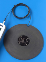
The accelerometer is triaxial. It should be set on the driver's seat, e.g. with adhesive tape.
The accelerometer should be connected to the right triaxial input of the instrument.
The cables of the accelerometer should not be pulled or bent, particularly near the sensor. They also should not be free oscillating to avoid fake results in the detected signal (triboelectric noise). Therefore you need to fix the cables near the transducer with adhesive tape.
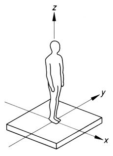
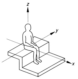
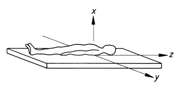
The norm ISO 2631 prescribes the orientation of the reference system according to which the three components of the vector acceleration are detected:
Z axis parallel to the backbone;
Y axis parallel to the femoral heads line;
X axis orthogonal to the previous ones.
The directions along the axes are irrelevant for the measurement.
Before beginning a measurement session, you should note the position of the three sensor axes 1, 2 and 3 in relation to the three axes X, Y and Z defined by the Norm, in order to correctly interpret the axial components measured by the instrument.
The following figure shows the enlarged detail of the sensor housing, at the center of the disc: the three axes of the accelerometer (AXIS 1, 2 and 3) are clearly indicated: remember that "Axis 1" is measured by channel CH1, "Axis 2"by channel CH2, and "Axis 3" by channel CH3.
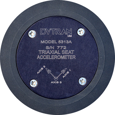
For the measurements on vehicles, the disc should be oriented so that axis 1 coincides with axis X in the figure (usually the vehicle direction),
axis 2 coincides with axis Y,
axis 3 coincides with axis Z (vertical axis).
4 axes measurement
In conjunction with the accelerometer in the seat, you can also use a monoaxial accelerometer to be mounted on the vehicle floor, right under the seat, or directly on the seat. The sensor should be oriented along axis Z.
In this case, you should load the 4-axis setup "WB SEAT 4 AXES".
You can use the HD3056B2 connected to the left input of the HD2030 with the cable HD2030CAB1-3M:
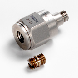
You can also use the accessories available on request for its mounting: threaded magnetic base, metal disc to be glued, etc.
By comparing the measurements done with the two accelerometers, you can separate the vibrations actually transmitted by the vehicle and the driver's movements, and therefore determine the attenuation capacity of the driver's seat.
Duration of the measurement
The total measurement time, that is, the number of acquired samples multiplied by the acquisition time per each sample, should be at least three-four minutes.
Generally, it is better to capture a greater number of short samples than a smaller number of long samples. This way, you can minimize the effect of possible interfering factors on the acquired signal, and ensure better accuracy.
To minimize measurement errors, we recommend to capture each sample at least three consecutive times, in the same operation conditions.
The measurements should have a duration representative of the vibrations transmitted to the worker's body in normal working conditions (road type, speed, etc.).
If the working conditions vary significantly, the frequency weighted r.m.s. acceleration should be specified for the different routes and operation modes.
Parameters to be measured
The WHOLE BODY type of measurement is set directly on the instrument menu with the parameter "Menu >> Settings >> General >> Measures >> Application = WB" or using the NoiseStudio software in "Instrument Manager >> Instrument Configuration >> General Page >> Application = WB Whole-Body". With this application the analyzer HD2030 performs the measurement according to ISO 2631.
Note: if you use the default setups ("WB SEAT 3 AXES", "WB SEAT 4 AXES" or "WB BACK 3 AXES"), the WB type of measurement is selected together with the other setup parameters.
Selecting the above setups, the W frequency weightings are applied to the acceleration level measured on the three axes of the right channel with the degrees of multiplication k, as required by the norm ISO 2631-1.
The values are indicated below:
-
X axis: Wd, k=1.4
-
Y axis: Wd, k=1.4
-
Z axis: Wk, k=1.0
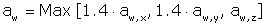
For the purpose of determining the daily exposure, the norm prescribes to consider the highest acceleration level detected on the three orthogonal axes, each multiplied by the proper k coefficient, as outlined below:
When you do not have a dominant acceleration level and the acceleration levels of at least two axes are comparable, it is better to evaluate the summation vector defined by this expression:
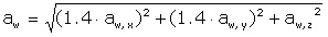
The instrument automatically records the levels on the three axes and the summation vector level.
From this relation, you can get the frequency weighted daily exposure referred to the 8 hours of work, conventionally indicated by the symbol A(8).
Later in the guide, we reported the measurement results evaluation criteria and some calculation examples of A(8).
Performance of the measurements
To perform the measurement, you have to set, according to your needs, the following parameters:
-
The input gain (Menu >> Settings >> General >> Measures >> Input Gain): you can set the greatest value but this should not lead to overload, as shown below.
-
The Integration Delay (Menu >> Settings >> General >> Measures >> Integration Delay). Delaying the integration beginning, allows stabilizing the signal and obtaining a more repeatable measurement. Usually 5 seconds are enough.
-
The Integration Interval (Menu >> Settings >> General >> Measures >> Integration Interval) can be used as a timer to automatically stop the measurement when the set time has elapsed. When set to zero, you can stop the measurement only manually.
To change the duration of the measurement interval, you can also press ENTER from the standard VLM page, until the "Tint" symbol is blinking. Then modify its value and confirm with ENTER.
To start the recording, press REC and START/STOP simultaneously.
At the end of the integration interval Tint, the instrument stops the measurement and prompts you to save the data: press SAVE.
The data saved in the memory can be downloaded to the PC using the NoiseStudio software (please see later in this guide).
The main problems encountered during measurement concern the connection cables between the accelerometer and the analyzer.
The connection cable and relative connectors can be the source of problems if they are damaged. You should always check that the cable and connector are not subject to stress during measurement.
You should reduce to the minimum the cable oscillations by fixing the cable to the vibrating object as close as possible to the accelerometer.
The polarization voltage of the accelerometers
Before performing the measurements, you have to check the accelerometers' polarization voltages. To do so, you only need to put the instrument in measurement mode, Menu >> Settings >> General >> System and check the polarization voltages Vpol of the 4 measurement channels. The correct polarization voltage is indicated by the accelerometer manufacturer and is normally between 8V and 12V.
A wrong polarization voltage could mean that the connection cable between the accelerometer and the instrument is faulty, or that there are contact problems between accelerometer, connection cable and analyzer.
Determination of the input gain
To determine the input gain correct value, you can perform a test measurement.
From an input gain of 20dB, you can perform a test measurement for a sufficient time to obtain a measurement representative of the characteristics of the tool being assessed.
If you do not see any overload indication, proceed with measurement. Otherwise, reduce the gain of 10dB and repeat the test.
If the overload indication remains, set a 0dB input gain.
If you still detect an overload, you should replace the accelerometer with one having a lower sensitivity.
Later you will see some examples of typical measurements that you can actually encounter.
To display the acquired measurements, you should install the NoiseStudio software and then download the data.
If the NoiseStudio software is installed, and the download to the PC has been performed, you can display the results.