|
|||||
Before beginning a measurement session, you should note the position of the three sensor axes 1, 2 and 3 in relation to the three axes X, Y and Z defined by the Norm, in order to correctly interpret the axial components measured by the instrument.
The sensor axes are indicated on its body, as in the HD3023A2 example:
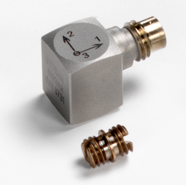
The triaxial sensors should be connected to the right input of the instrument: the detected measurements on axes "1", "2", and "3" are displayed, respectively, by channels CH1, CH2, and CH3.
A monoaxial sensor should be connected to the left input of the instrument, the measurement channel is CH4.
It is preferable to use a triaxial accelerometer for the measurement of the vibrations transmitted to the hand-arm system. As the coefficients and weightings are the same for the three axes in the calculation of the vector acceleration, you can perform the measurement even orienting the accelerometer axes in different directions from those of the basicentric system defined by ISO 5349-1.
If you are using a monoaxial accelerometer, you should orient the sensor along the axis of greater exposition. The vector acceleration value will be determined, in this case, applying a degree of multiplication to the value measured along the main axis.
This multiplication coefficient will go from 1, for tools with a well-defined dominant axis, to 1.7 when you are assuming that the acceleration is the same for all the axes. You can use a coefficient of 1 only when the acceleration along the non dominant axes is lesser than 30% of the one on the main axis.
The reference norm ISO 5349-2 recommends the sensors' position for various machine tools.
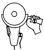
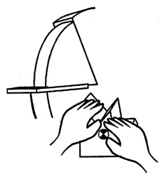
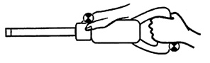
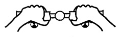
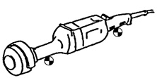
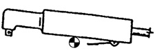
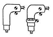
In the following figures, the accelerometer position is indicated by a black and white circle. |
| Chainsaw |
 |
|
| |
||
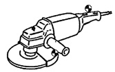
| Grinder |
 |
|
| |
||
| Fixed grinder |
 |
|
| |
||
| Pneumatic hammer |
 |
|
| |
||
| Tool |
 |
|
| |
||
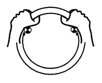
| Handwheel |
 |
|
| Brush cutter | 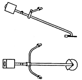 |
|
ISO 5349 is a general norm. It does not define the operation and practical details of each tool: the selection of the sensors' position can be difficult.
In these cases, you can use the ISO 8662 family of norms, which describe the procedures for the measurement of the vibrations of different tools in laboratory or reference conditions.
From this series of norms, we created the following table showing the sensors' position per each tool.
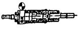
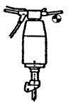
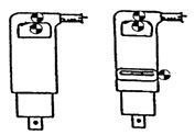
Pneumatic hammer |
 |
 |
 |
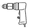
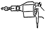
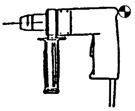
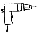
| Driller |
 |
 |
 |
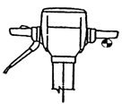
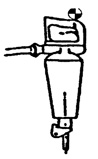
| Concrete-breaker |
 |
 |
 |
| Rammer | 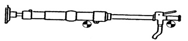 |
||
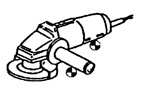
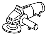
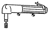
| Angle grinder |
 |
 |
|
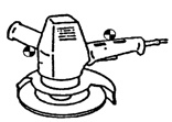
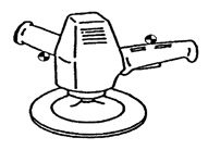
| Vertical grinder |
 |
||
| Straight grinder |
 |
||
| Screwdriver | 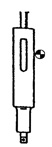 |
 |
|
 |
 |
||
| Polisher Sander |
 |
 |
 |
| Mill | 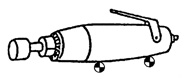 |
 |
|
| Stapler Saddle stitcher |
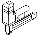 |
||
For the measurements, you can use the HD3023A2: a miniature triaxial accelerometer with nominal sensitivity of 10mV/g and measurement interval of +/-500g.
The connection cable between the accelerometer and the HD2030 is the HD2030CAB3-3M:
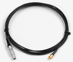
The cable should be connected to the right triaxial input of the instrument.
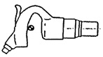
When peak accelerations repeatedly exceed 1000g, you should use an accelerometer for shock measurements with sensitivity of 1mV/g and resonance frequency higher than 50kHz.
In this case, you can use the HD3200B5T monoaxial accelerometer that has a measurement interval of +/-5000g. You should orient it so as to measure the accelerations along the dominant axis.
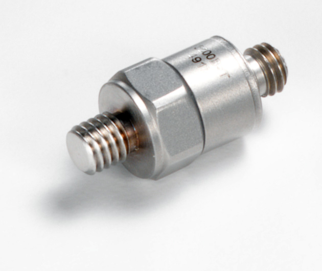
The accelerometer is connected to the HD2030 left input using the HD2030CAB1-3M connection cable.